Preprint ANL/MCS-P747-1298
The GRF, a high-performance IP switch from Ascend
and IBM, is the first backbone network switch to offer a media card that
can directly connect to an SP Switch. This enables switch attached hosts
in an SP complex to communicate at near SP Switch speeds with other GRF
attached hosts and networks.
The SP Switch is the key communications component of an SP complex making high-performance communications possible for use in parallel and distributed applications. For applications running on a single SP complex with little or moderate external communications requirements, conventional Ethernet and ATM networking may be adequate. With increasingly parallel and distributed applications comes an increasing demand for connectivity between an SP complex and external networks and hosts.
The SP Switch offers attached hosts a theoretical 960 Mb/second bi-direction data-transfer (our P2SC nodes). Given the switch design, conducting an aggregate switch throughput test would be a difficult task. Our division's backbone is entirely ATM OC-12 based (622 Mb/second) with an OC-12 uplink. Most divisional servers are either on switched 100 Mb/second Ethernet or ATM OC-3, with one large graphics machine on OC-12.
In this environment the best we could offer between the SP and the division backbone or other network hosts was ATM OC-3 (155 Mb/second). The GRF offers 1 Gbit/second per card with aggregate bandwidth of 4 or 16 Gbits/second (GRF400 and GRF1600 respectively). Using the GRF therefore has the potential of increasing our SP's connectivity by up to a factor of 4.
The primary reasons we evaluated the GRF were to determine theoretical network performance improvements we could achieve versus existing networking, to determine how much real-world gains applications could expect, and to assess the overall installation, configuration, and management process of the GRF within an SP complex.

Our IBM SP contains:
It is important to note that the 80 SP3 thin nodes are a compute pool managed through a scheduler. This set of nodes, plus some of the other nodes used for interactive development work, may all require high bandwidth communications.
Processor Type Number Memory Memory Banks Clock CPU Type Disk SP3 thin nodes 80 256 MB 2 120 MHz P2SC 9 GB SP3 thin nodes 8 512 MB 4 120 MHz P2SC 9 GB SP3 wide nodes 8 512 MB 4 135 MHz P2SC 9 GB 8-way SMP 2 1 GB 4 66 MHz 604 6 GB/node
In our environment we used the gateway approach
by setting aside a single SP wide node with an ATM OC-3 interface providing
TCP/IP gateway services for nodes on the switch. Key disadvantages of this
approach include the (miss)use of a host as a network device and the capacity
limitations and bottlenecks imposed by that host. It also limited our ability
to provide high-performance switch-to-multipoint connectivity. Under heavy
network load our single wide node could easily achieve 70-80% CPU utilization
just forwarding traffic through its single ATM interface. Alternatively
we could have outfitted additional hosts with ATM interfaces; an approach
that could impose management headaches, significant costs for interfaces
and switched ports, and still limited individual connections to single
OC-3 speeds.
The GRF Embedded OS is a Unix variant making configuration and management similar to configuring network interfaces on a Unix host. The high-levels configuration steps are:
After upgrading our SP to the required software level, we encountered one configuration issue: ARP has to be running over the SP switch. Our SP was not running ARP on the switch and SP networking requires that ARP be running on all the switch interfaces or none at all. One of the key implications of running ARP is how TCP/IP addresses are assigned to SP switch nodes. Without ARP, addresses must sequentially match node numbers, whereas with ARP more flexibility is possible. Our main difficulty came from a lack of reconfiguration documentation, all we could find was how to enable ARP during initial SP complex configuration. To avoid the outage associated with reconfiguring the entire complex and pushing the changes though a process called a customize we contacted IBM technical support looking for a faster and simpler approach. The procedure suggested should have required minimal downtime but ended up causing significant problems because the configuration change disappeared on a reboot. It took extensive investigation by us and IBM to discover that the changed ARP parameter needed to be saved to the boot device using the command savebase. We would recommend following the standard customize process for changing ARP on the entire complex, in spite of the outage it would impose.
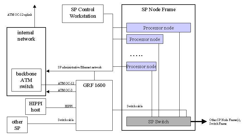
Since the GRF behaves as a switch node it must be attached to a switch port on a node frame and cannot be attached to a switch frame. This made it necessary to attach it to a frame containing wide or high nodes with unused switch ports. The last node in our last frame was a wide node, so we were able to attach the GRF to the switch port for the 16th node slot and therefore above all other nodes in the complex. When the GRF is attached to a switch port on a node frame it also must be assigned a unique node number and switch node number within the complex. These numbers must be determined and entered via PSSP when configuring the GRF Extension node and it's SP interface. It's essential to understand the relationship of SP node number to SP switch node number as described in the PSSP Installation and Configuration Guide.
The GRF connects to an SP switch port using a standard switch cable.
Because we evaluated the GRF attached to a production
system we were concerned about maintaining external connectivity during
GRF reconfigurations or faults. To achieve this we elected to maintain
all existing external network connections (primarily our ATM OC-3 gateway)
and to configure the Unix gated daemon to enable most of our nodes to use
the GRF by default, but to automatically fail over to the ATM OC-3 gateway
if the GRF wasn't available. This type of route configuration was also
necessary between the GRF and our router to ensure that inbound traffic
used the GRF whenever possible instead of the ATM OC-3. This multiple gateway
approach did introduce more management complexity into our environment.
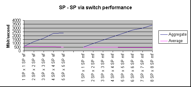
To determine how effective the GRF switch interface handles switch traffic we first measured the performance of the switch interface on an SP wide node. Although this value most likely does not represent the actual switch port capability, it was the closest we could come, and also provided us with a comparison value. SP wide node to SP wide node tests measured up to 610 Mb/second (single direction). Multiple SP wide nodes to a single SP wide node achieved 620 Mb/second. Bydirectional tests results were 640 Mb/second. Published bydirectional limits are 960 Mb/second. These were not achievable because our SP wide node was CPU bound at 640 Mb/second.
In an attempt to measure aggregate switch capacity we conducted a small 8 way test between nodes on different frames. This experiment measured aggregate throughput near 3.5 Gbit/second with near linear scaling in the 1 to 8 way range. This is consistent with the switch design.
Graph 1 - switch performance.

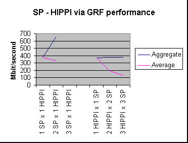
To test the GRF's HIPPI interface we were able to attach it to an 8 CPU Onyx. The following graph shows SP node to HIPPI node performance results.
Graph 2 - GRF performance forwarding between SP switch adapter and HIPPI.

The first issue we encountered with the HIPPI test dealt with SP to HIPPI traffic. One SP node to HIPPI performance was 380 Mb/second, two SP nodes achieved 660 Mb/second aggregate, and three SP nodes crashed our switch. We suspect that three nodes was enough to saturate the HIPPI interface, which probably exposed a backoff or throttling problem. The second issue involved test in the opposite direction, HIPPI host to SP. A single process achieved 370 Mb/second. Two HIPPI host processes to two SP hosts showed 190 Mb/sec (380 aggregate). Three HIPPI host processes to three SP hosts at 127 Mb/sec (still 380 aggregate). It appears that we encountered either a host HIPPI outbound or GRF HIPPI inbound limit of 380 Mb/second.
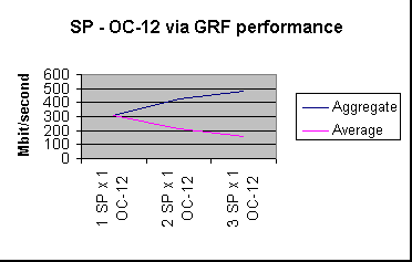
To test the GRF's performance forwarding from the SP switch adapter to OC-12 we attached both the GRF and a 16 CPU Origin2000 host via OC-12 to our ATM OC-12 backbone and configured an ATM PVC between the GRF and the Origin2000 host. It is important to note that this test involved a beta ATM driver for the Origin2000 and no tuning. The graph below show performance between 1, 2, and 3 SP hosts, through the GRF switch adapter, GRF OC-12 adapter, two switches at OC-12, and a single OC-12 adapter on an Origin2000 host.
Graph 3 - GRF performance forwarding between SP switch adapter and OC-12.

The above numbers demonstrate the GRF's ability to effectively forward SP switch adapter traffic through it's OC-12 adapter. A reverse benchmark, from the OC-12 host through the switching and GRF fabric to multiple SP switch hosts yielded very poor performance which we attributed primarily to the beta ATM driver on the Origin2000 host.
In the above tests we benchmarked specific pairs of GRF adapters looking for point-to-point performance between an SP complex and a target HIPPI or ATM host. To measure the performance limits of the GRF SP switch adapter and benchmark more than two GRF interfaces at a time we conducted a test from 5 SP nodes to 2 HIPPI targets and 3 OC-12 targets. The observed results of 900 Mb/sec were the highest we've benchmarked through a single GRF SP switch adapter.
GRF backplane performance limits are irrelevant because it theoretically scales at 1 Gb/second per port. We suspect that a three card test (HIPPI, OC-12, SP Switch) will not strain the backplane. Additional fast interfaces would be necessary to conduct this type of test.
We conducted application level benchmarks using MPI RIO. These test involved one or more instances of an application running on a client performing remote I/O to a server. In the first set of benchmarks the clients ran on the SP and communicated to the RIO server which was directly attached to the GRF via ATM OC-3. Key measurements included a round-trip latency of 1.214 ms. and anywhere from 10.69 MB/s (64% of peak network rate) to 98%. We found the ability to achieve 98% of the theoretical ATM OC-3 peak of 133 Mb/second to be quite impressive.
A second set of MPI RIO tests used another OC-3 as the server, except this server was one ATM switch away from the GRF and involved a hop through our router which is OC-3 attached. These test achieved about 66% of theoretical peak performance for ATM OC-3. We believe these results suggest several things about downstream connections through the GRF. The most obvious is that for best results machines collaborating with the SP should be attached directly to the GRF. When the peer is not attached to the GRF, extra care should be taken to understand the route and relative performance of the links. In this case putting peers on the other end of an OC-3 limited router, which is serving many other hosts, imposes a significant bottleneck. If SVCs had been available we could have avoided going through our router. Given our large number of ATM hosts and use of LANE, we could not have effectively managed a manual PVC based configuration.
Based on the above results and IBM/Ascend provided
theoretical limits we believe if multiple SP hosts concurrently communicate
with multiple GRF attached hosts the first component to saturate would
be the SP switch interface on the GRF. GRF literature indicates capacity
for 1 Gbit/second per adapter card, so in theory an SP switch adapter should
be able to operate at near peek bydirectional performance. We were unable
to perform real world tests demonstrating adapter saturation. Our
best results through the GRF were 660 Mb/second, a value slightly above
our best switch performance for a single SP node. If aggregate throughput
beyond a single SP switch interface is required it is technically feasible
to have multiple GRF switch adapters on the same switch. In such
a configuration performance could be optimized by connecting the GRF to
multiple SP node frames.
On a couple of occasions we found the GRF's date and time to be off by as much as a month. We were unable to find a cause although it appears that it happens on reboot.
A software bug would cause broadcasts out the HIPPI interface to fill the ARP table and bring down the interface. The temporary solution was to disable outbound broadcasts on HIPPI the interface.
In a large ATM infrastructure managing PVCs is an unwieldy process. In our environment with 3+ switches, a router, and many ATM hosts, creating PVCs between the SP and various ATM hosts would require us to define many PVCs. Since this would be a network management headache we feel that SVCs are essential for large ATM environments wanting to integrate the GRF.
Additional information would have been useful
on how to enable ARP on the switch,
In an environment such as ours, where high-speed
connectivity from an SP complex to external hosts is required, nothing
can compete with the GRF for performance. Using the GRF to connect multiple
SP switches would also provide unrivaled networking performance.
October 1998