|
MeshKit
1.0
|
|
MeshKit
1.0
|
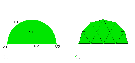
In this example, an example of meshing graph traversal is given where graph nodes create other graph nodes dynamically during the setup phase. Consider the generation of a mesh for a surface bounded by two geometric edges and vertices:

For the starting mesh graph, the user specifies a "trimesh" meshing operation, assigned to the surface:

Starting the setup traversal, the trimesh operation determines that it needs a mesh for the bounding edges, and creates a graph node representing that operation (an EqualEdgeMesh meshing operation applied to edges e1 and e2). Continuing the traversal, the setup operation on the EqualEdgeMesh node determines that the two bounding vertices must be meshed; this is accomplished by creating a VertexMesher graph node, applied to vertices v1 and v2. The setup operation on the VertexMesher node creates no new graph nodes, so the setup traversal terminates at the root node. The graph resulting from the setup traversal appears as:

with user-specified nodes colored cyan, and automatically-created nodes colored magenta. Note that a given node can represent a meshing operation applied to multiple entities in the BREP model. In practice, this greatly simplifies the mesh graph, with no loss of detail in the overall meshing process.
The execute phase traverses the graph in the forward direction, generating mesh for the geometric vertices in the first (non-root) node, for geometric edges in the second node, and finally the surface mesh in the third node:

Top: MeshKit: A Library for Mesh Generation Prev: Data Model Next: Geometry, Mesh, Relations Interfaces